 Thrust bearings
|
Mode |
Tool |
Tool set |
|
Modes for L’outil Insertion de symbole |
Thrust Bearing
|
Machine Components |
The Thrust Bearing tool and Thrust Bearing - 3D tool share the same position on the tool set. Click and hold the mouse on the visible tool to open the Sous-outils list and select the desired tool.
To insert a thrust bearing:
Click the tool and mode.
Click to place the object, and click again to set the rotation. The first time you use the tool in a file, a properties dialog box opens. Set the default parameters. The parameters can be edited later from the Object Info palette.

Click to show/hide the parameters.Click to show/hide the parameters.
|
Parameter |
Description |
|
|
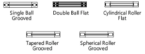
Bearing Type |
Select one of the bearing types |
|
|
Raceway Style (Single Ball, Double Ball, and Cylindrical Roller types only) |
Choose either grooved or flat |
|
|
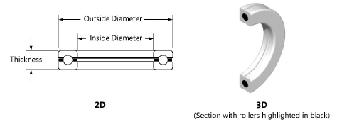
Inside Diameter |
Specify the inside diameter of the bearing |
|
|
Outside Diameter |
Specify the outside diameter of the bearing |
|
|
Thickness |
Enter the width of the outer ring |
|
|
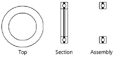
View (2D only) |
Select the 2D view
|
|
|
Show Retainer(s) |
Displays the bearing retainer(s); Show Detail must also be selected to view the retainer(s) in 2D bearings |
|
|
Show Detail (2D only) |
Indicate whether to display a detailed view of the 2D bearing (including balls) |
|
|
Show Center Line (2D only) |
Draws the bearing with center lines |
|
|
Section (3D only) |
Draws a section of the bearing |
|
|
Highlight Rollers (3D only) |
Highlights the rollers within the bearing in black |
|


